Full Technical Report Download
Download Full Technical Report Download this for most detail or keep scrolling for overview of my main contributions
Autonomous Search and Rescue Robot
FINALLY!! A school project that is all about building something and solving a problem. We were applying theory to a physical thing and troubleshooting...it is just perfect. The late nights, early mornings, smacking your head against the desk because you have no idea why it isnt working, then you do that for way too long, take a walk and in the middle of that you have that sudden realization that you can try one last thing so you race back and try it and it works. This project is the definition of that feeling. For 3 months, I have never seen a group work as hard as we did, commit so much time and effort, yet still find time to laugh and love spending time together. This is another one of those projects that continued to make me fall in love with engineering and I am happy to share it with you.
13s Run - The Best
We guessed on the PD tuning because we had never done this before so thats why its jittery.
15s Run
The second run was the same as this one but this our first scored run that we tuned as best we could.
Full robot
360 degree video walkthrough
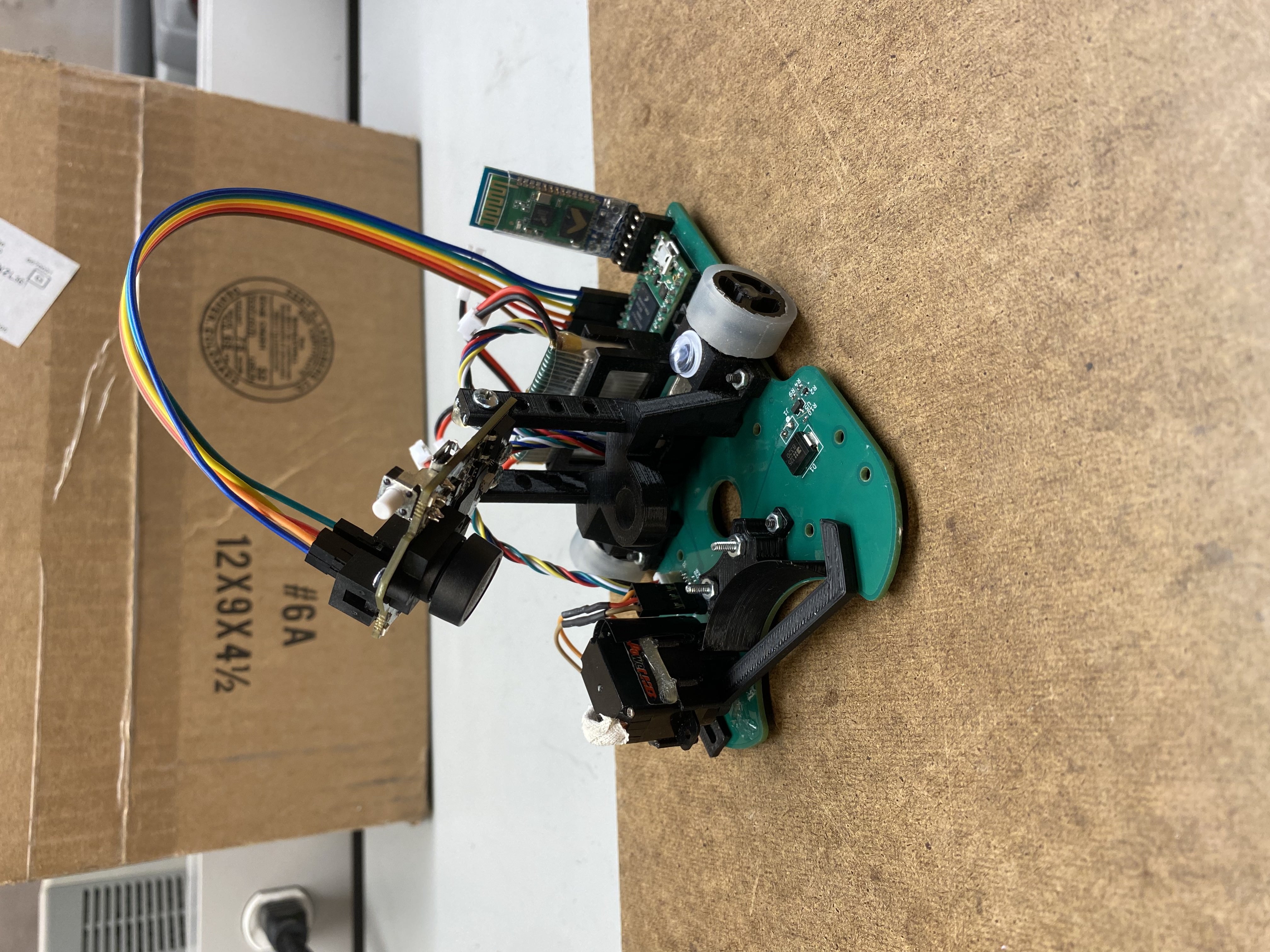
Full robot - Front
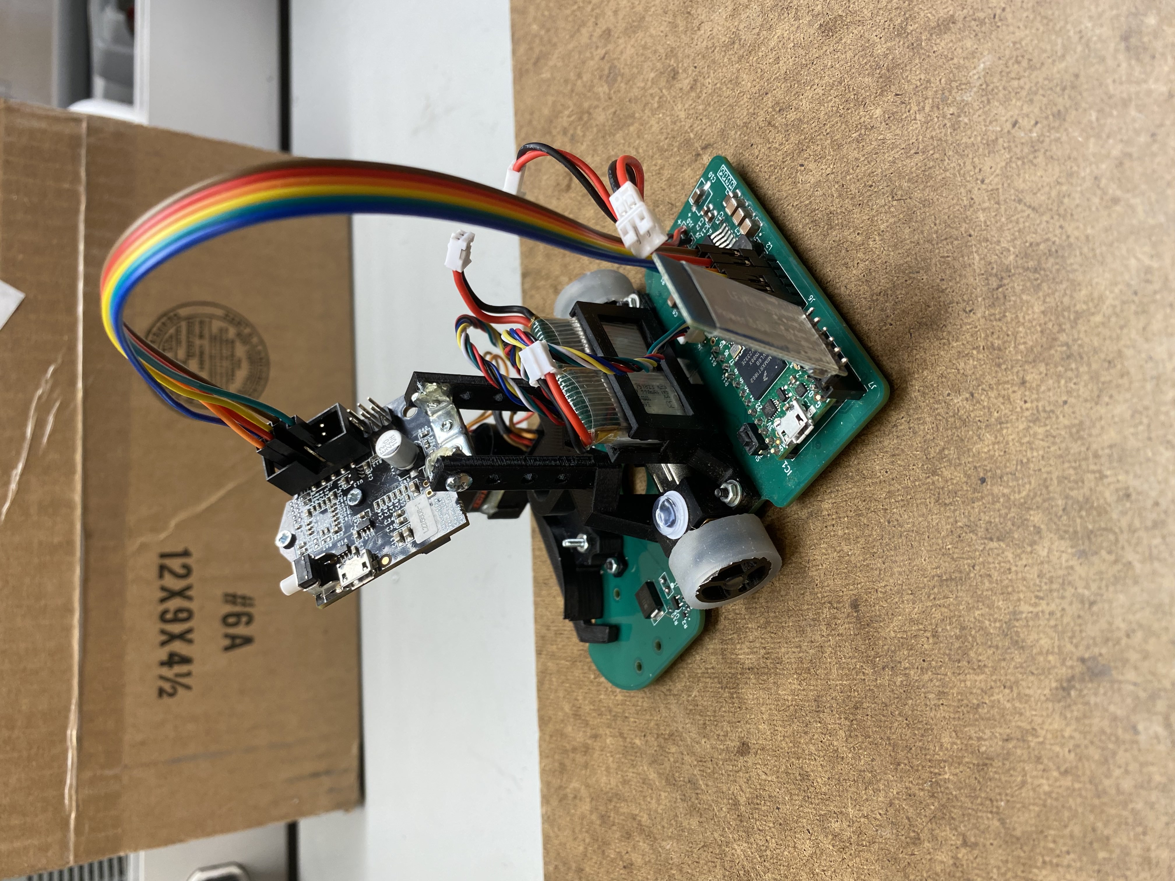
Full robot - Back
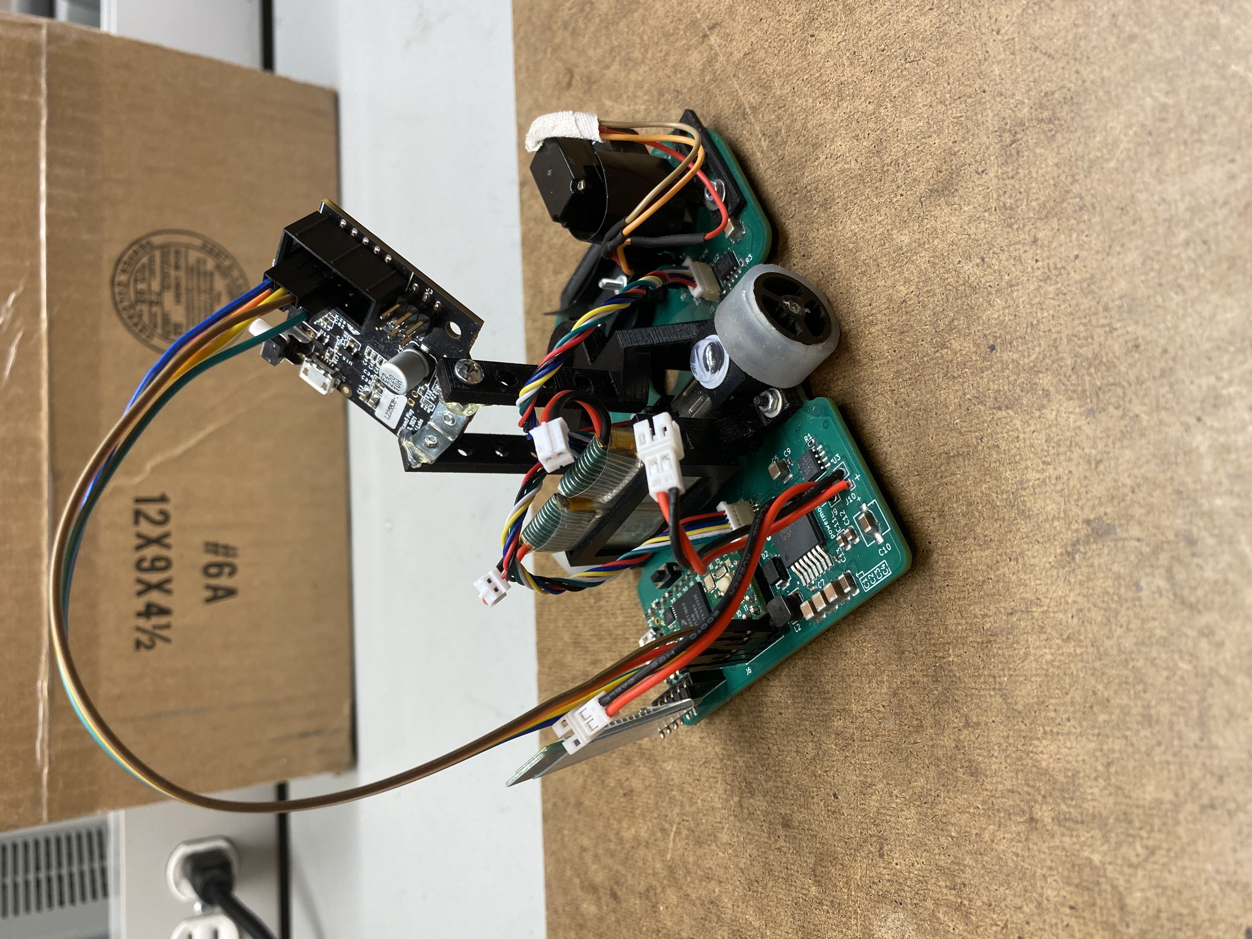
Full robot - Side
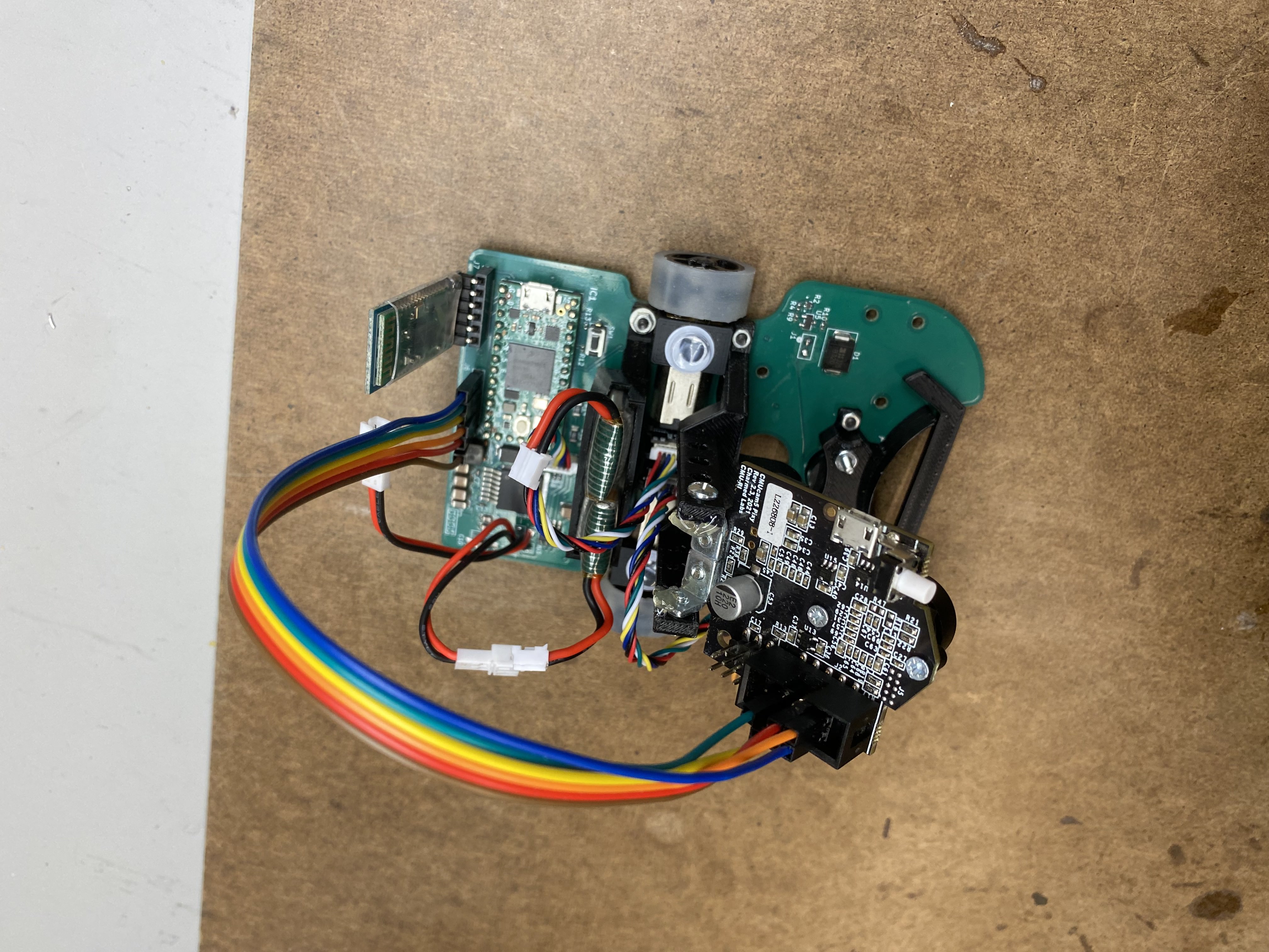
Full robot - Top
Project Background and Summary
As part of my most recent semester, I completed MTE 380, a mechatronics design course where student teams are tasked with developing a complete engineering solution from concept to final product in just 3 months. Our goal was to build the most optimized robot possible: one that could autonomously follow a line, retrieve a LEGO figure, deliver it to the nearest green box, and return to the starting position, all while being fast, lightweight, and highly reliable.
We decided to fully commit to that challenge and see what we could end up with.
After the 3 months, we ended up with a 131g autonomous search-and-rescue robot that completed its mission in just 13 seconds with a 100% reliability score (3/3 runs).
The robot featured computer vision for line following, encoder-based PD control, a custom 4-layer PCB chassis, custom 3D printed and silicone-molded wheels, and a LEGO figure gripper mechanism. We also designed and tested a suction-based downforce system (inspired by micromouse robots), which was ultimately left out due to power constraints, but this project pushed us to explore new ideas and validate through testing.
With well over 1200 team hours including countless late nights and a few all-nighters, we poured everything we had into this project. We designed and tested 15 gripper arms, 70 custom impellers, and 2 custom PCBs. From coding and tuning our PD controller to debugging every detail of the mechanical and electrical systems, we iterated continuously right up until the last minute.
Under a tight timeline, we focused on squeezing out every bit of performance optimizing for high speed, low mass, and high reliability.
The final result? First place in the class, with a performance score 68x higher than the second-place team.
Huge shoutout to the team for every early morning, late night, frustrating bug, last-minute idea, and breakthrough moment. I'm incredibly proud of what we built and even more proud of the people I built it with. Shoutout Nathan Rowe, Natalie Tsang, Chelsea Dmytryk, and Lili Strong for being the best teammates I could have ever asked for, be sure to check them out on LinkedIn!
Huge shoutout to the team for every early morning, late night, frustrating bug, last-minute idea, and breakthrough moment. I'm incredibly proud of what we built and even more proud of the people I built it with.
My biggest takeaway? It takes a team of like-minded, dedicated people to do something amazing.
My Role
In this 5-person design challenge, I led the development of the suction system, mechanical-electrical integration, and co-designed the PCB. I also took a systems integration and project management perspective to ensure the electrical, mechanical, and software subsystems worked together reliably under tight deadlines. Key contributions included:
- Designing and testing custom impellers and suction skirt geometries to increase theoretical cornering speed
- Casting custom high-μ silicone wheels for optimized grip
- Co-designing a 4-layer PCB chassis, including low-latency routing for encoders and signal lines
- Tuning and debugging PD controller and general state machine flow
- Co-designing a servo gripper system with foam dampening to reduce vibration error and a sloped LEGO backboard to prevent figure snagging
- Weight optimization through sourcing components and calculating minimum system requirements
- General project management and system integration
FOR MORE A MORE DETAILED BREAKDOWN OF EVERYTHING PLEASE DOWNLOAD THE FULL TECHNICAL REPORT AT THE TOP OF BOTTOM OF THE PAGE!!!!
Also note that although I was the project manager, after we set initial deadlines, we all worked together almost 100% of the time so there was almost no managing people, it was mostly making sure key decisions were made at critical times and making sure everybody stayed healthy and excited about the project! We were definitely all 1000% on board with the mission which was a huge part of our success. Finally, thanks to: Nathan Rowe, Natalie Tsang, Chelsea Dmytryk, and Lili Strong for making this project possible! None of this would have been possible without who I believe is the best team I could have ever asked for! Make sure you check them out on LinkedIn!
Performance Index (PI)
The competition used the following metric to determine success:
$$ PI = \frac{C}{R \cdot m \cdot t^2} $$
- R = number of failed runs (0.75 for 3 successful runs, 0.9 for 2 successful runs, 1 for 1 successful run)
- m = robot mass (g)
- t = time to complete task (s)
This incentivized designs that were light, fast, and reliable. Our 131g robot completed the full challenge in 13.0 seconds, succeeded in all 3 runs, and scored 68x higher than the next closest team.
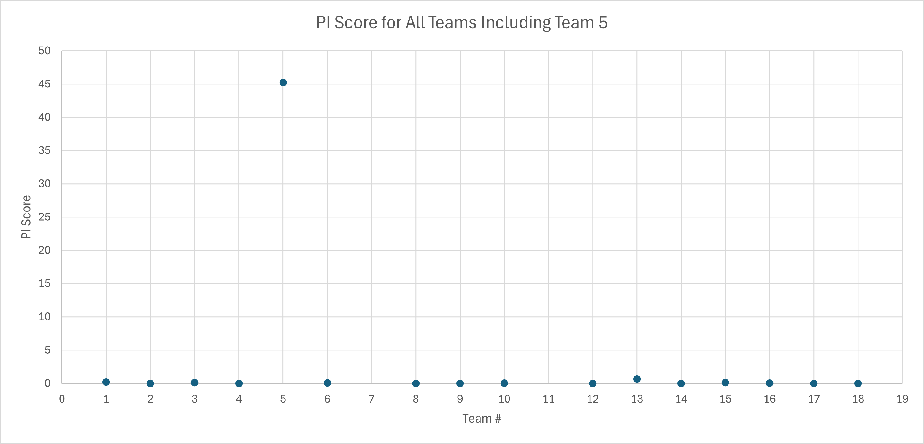
Competition Results With Our Team
68x higher than second place
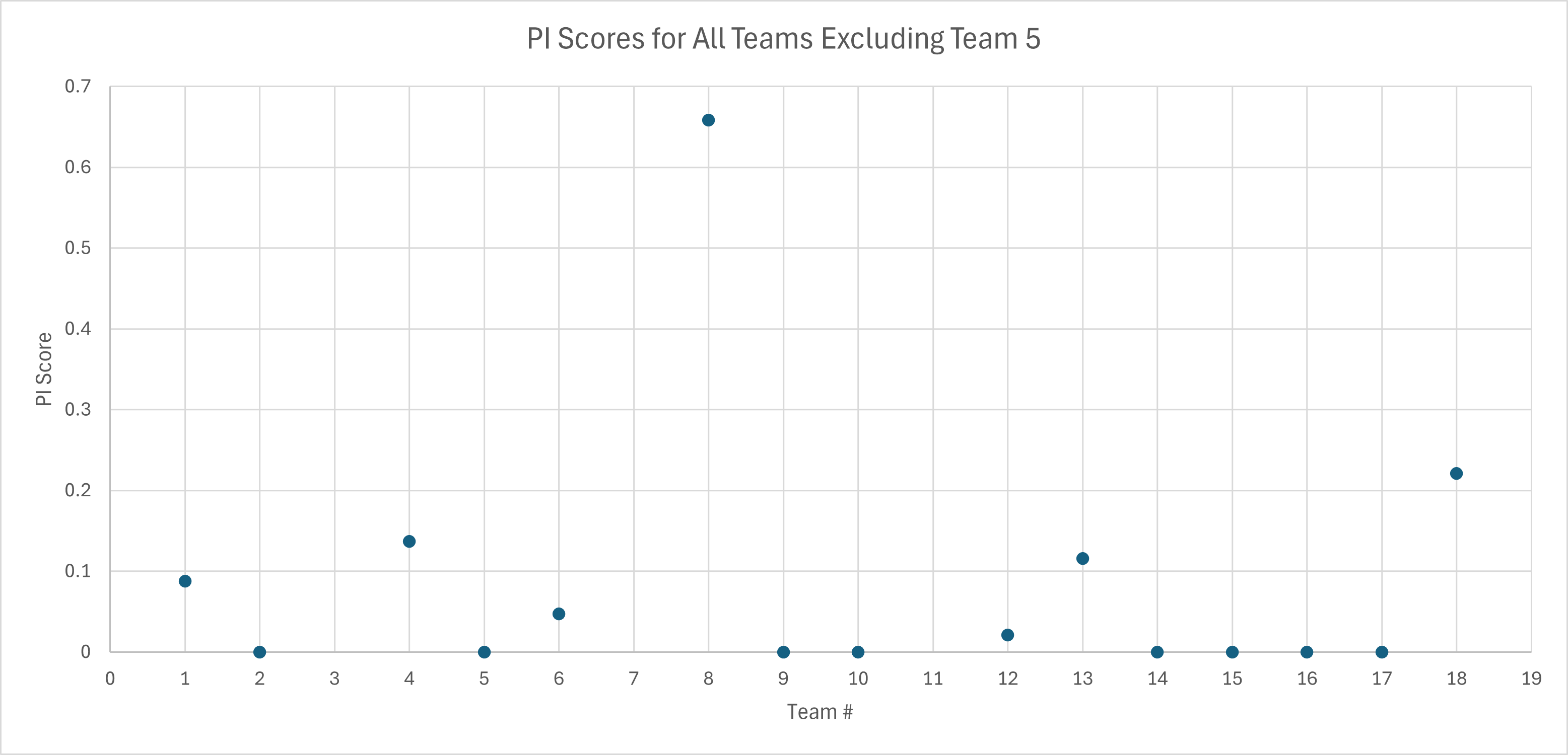
Competition Results Without Our Team
Suction Downforce System
To increase cornering performance beyond the friction-limited cap, I led the development of a suction fan system with custom impellers and skirts. While ultimately cut from the final run due to power instability, the system was fully functional and validated through structured paramaterized testing.
Why Downforce? Derivation from First Principles
Since there were so many turns on the course and knowing our motors were capable of such high speed (over 3 m/s), I knew the cornering speed is where we would be limited so I started attacking that problem from first principles. Starting with the FBD for our robot around a corner, it is clear why additional downforce is required.
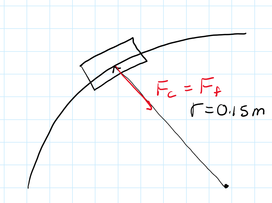
FBD of robot turning
We start from Newton's Second Law:
$$ \sum F = ma $$
Because the robot is cornering:
$$ \sum F_{\text{radial}} = ma $$
From a free-body diagram, the only force contributing to centripetal acceleration is friction:
$$ F_c = F_f = \mu F_N $$
And since \( a = \frac{v^2}{r} \) for circular motion:
$$ \mu F_N = m \left( \frac{v^2}{r} \right) $$
Without Suction (No Artificial Downforce)
Letting \( F_N = mg \):
$$ \mu mg = m \left( \frac{v^2}{r} \right) $$
Simplifying:
$$ v = \sqrt{ \mu r g } $$
This gives a fixed \( v_{\text{max}} \) once \( \mu \) is known. Substituting values:
$$ v_{\text{max}} = \sqrt{1.2 \cdot 0.15 \cdot 9.81} \approx \boxed{1.33 \, \text{m/s}} $$
With Suction (Artificial Downforce)
Now, let the normal force be increased by suction downforce \( F_d \):
$$ \mu (mg + F_d) = m \left( \frac{v^2}{r} \right) $$
Solving for velocity:
$$ v = \sqrt{ \frac{r \mu (mg + F_d)}{m} } $$
Substituting values:
$$ v = \sqrt{ \frac{ 1.2 \cdot 0.15 \cdot \left[ (0.131)(9.81) + 0.148 \right] }{ 0.131 } } \approx \boxed{1.40 \, \text{m/s}} $$
With \( \mu = 1.2 \) determined experimentally using a ramp and sample, based on the relation: $$ \tan(\theta) = \mu \quad \text{at slip} $$
The predicted cornering velocity under various downforce levels is summarized below, including the measured value.
| Downforce Level | Normal Force (N) | Max Speed (m/s) |
|---|---|---|
| None (gravity only) | 1.285 | 1.33 |
| +131g (1x mass) | 2.570 | 1.88 |
| +262g (2x mass) | 3.855 | 2.30 |
| +393g (3x mass) | 5.140 | 2.67 |
| Measured: 0.148 N | 1.433 | 1.40 |
Although the theoretical max cornering velocity only increased by 0.07 m/s, this would still boost our performance index by approximately 3% which is alot considering we are trying to push the limit as much as possible. Also note that these results can definitely be better with more time and simulation and research put in. This was just a small piece of the puzzle that I was able to achieve in a short time span starting from scratch!
Impeller Design and Parameter Testing
I chose to do some preliminary research about impeller desings and realized it is a very dense subject. After I started to see lots of different pictures and information on impeller design, I was left with 2 options.
- Try to calculate and make the best impeller purely by theory and then simulate the results and iterate on a computer
- Determine the parameters I need to change about impellers and 3D print a tonne of them and do testing to see how different parameters affect the performance then "create" the optimal impeller from there
Given the timeline, I felt like learning CFD well enough and given the potential for me to mess up calculations or simulation, I opted for the second option. This meant I would 3D print as many impellers as required to vary 1 parameter at a time. Below I list the parameters I changed and also a picture of just a fraction of the impellers I tested.
- Blade count (2-14)
- Blade pitch (15-35mm)
- Blade curvature (45-60 degrees)
- Diameter (12-30mm)
- Height (10-15mm)
- PCB cutout hole diamter (10-20mm)
- Revolved cut shape and dimension on impeller (triangle, 1/4 circle, none)
- Style: radial vs compression
Each impeller was tested on a 3D printed robot-shaped test chassis over five timed runs down a 25° 1' ramp using a fixed 5V, 0.5A power supply on the motor. Below is a video of what my test setup looked like:
Suction Testing Setup
I took a tile from the course and 3D printed a mock chassis and used to it iterate through various impeller designs.
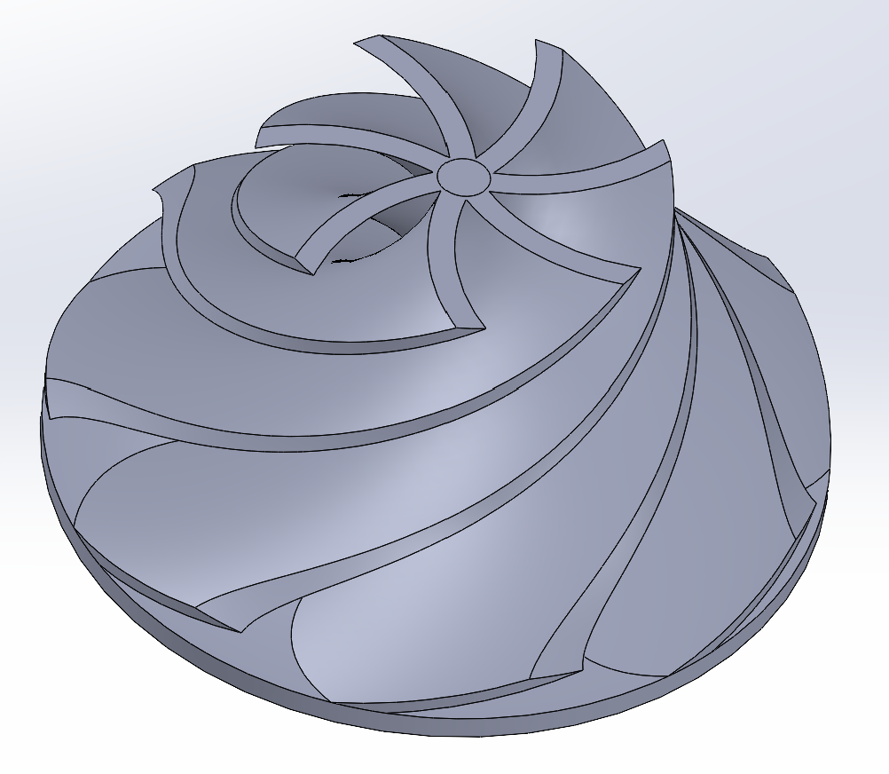
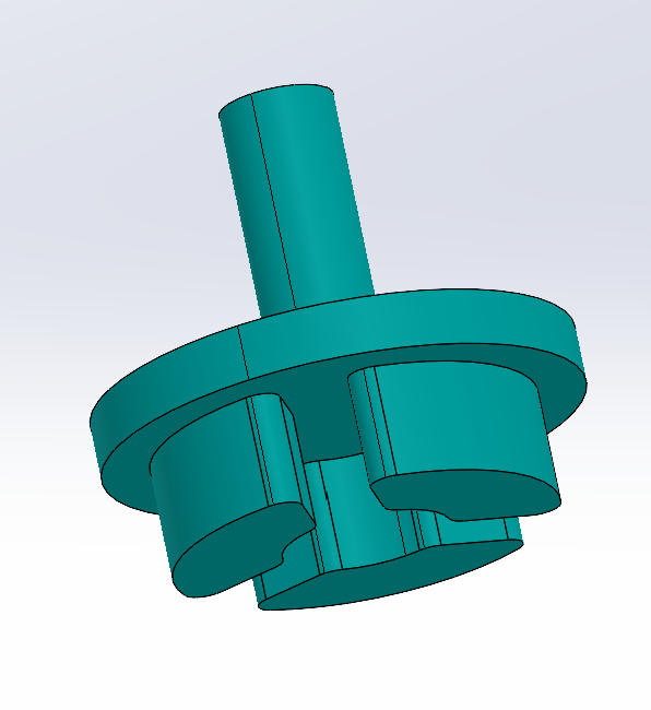
Example Compression Style Impeller
Example Radial Style Impeller
Below compares the main takeaways, mainly a 5 bladed radial impeller design is much better than any compression style. They both shared the similarity that performance was clearly peaked at 5 blades and fell off extremely once there was an increase to 7 or a decrease to 2. The most surprising thing was 2 blades had similar results to 7 blades and that 3 blades was better than 6 blades, but 5 was a clear winner with 4 not trailing too far behind.
| Impeller Type | Avg. Ramp Time (s) | Relative Traction |
|---|---|---|
| No Fan | 0.84 | 1x |
| Compression (5 blade) | 21.13 | 25x |
| Final Radial (5-blade) | 55.12 | 65x |
Skirt Design and Testing
The skirt system needed to create a seal against the course while being low friction and not catching on the lips between the tiles on the course. I iterated a few designs listed below and shown:
Skirt systems tested
- Flexible thin foam + duct tape
- felt + thin tape
- felt+mylar (thick document cover plastic from dollar store)
- PLA side rails + thin tape + thin dynamic PLA plate
Below are the 4 versions
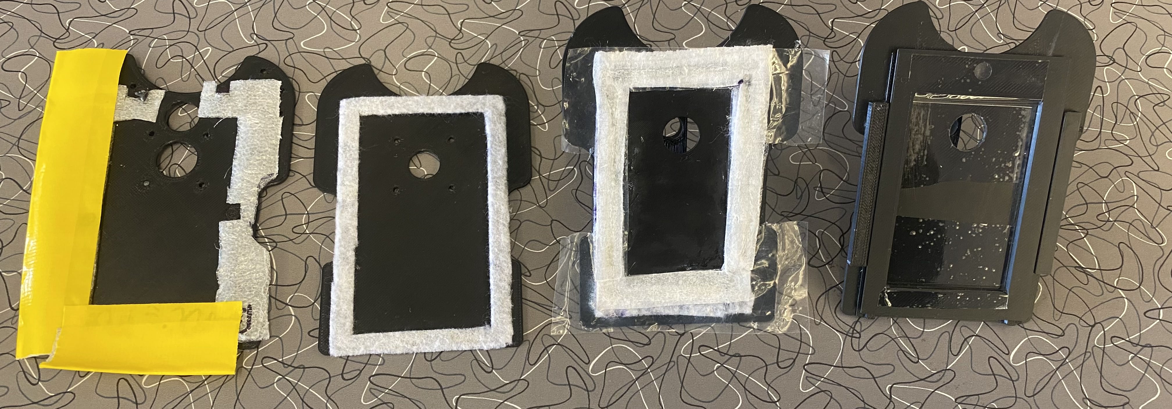
4 Skirt Prototypes
The final version used
- 3D printed side rails for lateral sealing
- Tape on the front and back for airflow containment
- Angled PLA ramp to prevent snagging on floor transitions
The final version also was able to move up and down while still maintaining a good enough seal to create some sort of suctioning effect thanks to the side rails.
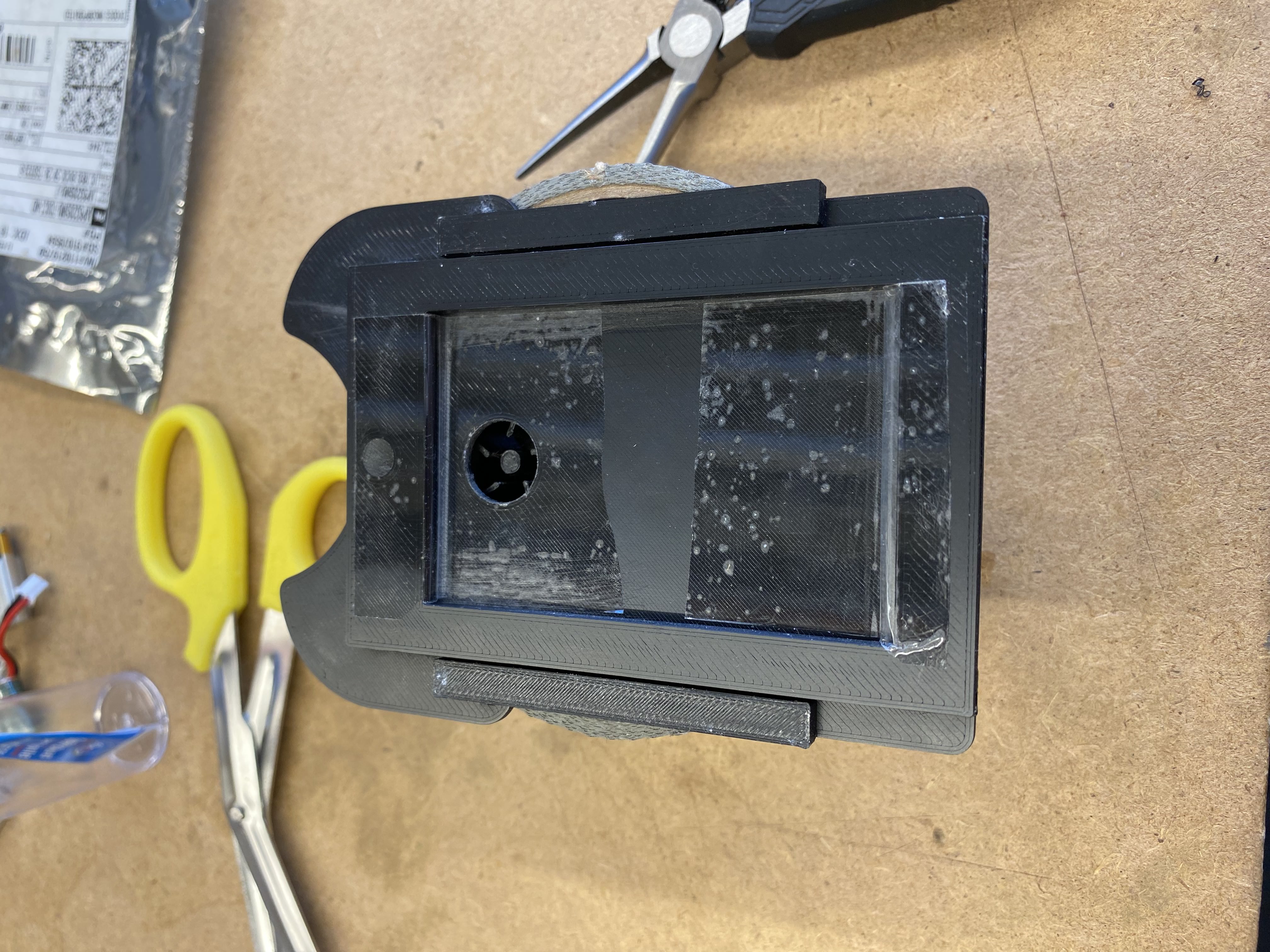
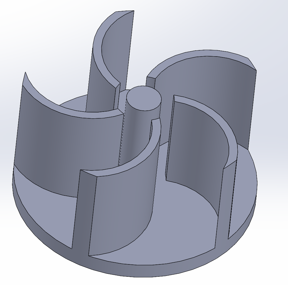
Final 3D Printed Skirt
It is taped loose enough to wiggle. Also note this picture does not have the roller ball hole cut in it yet or the ramp easily shown so please see the CAD.
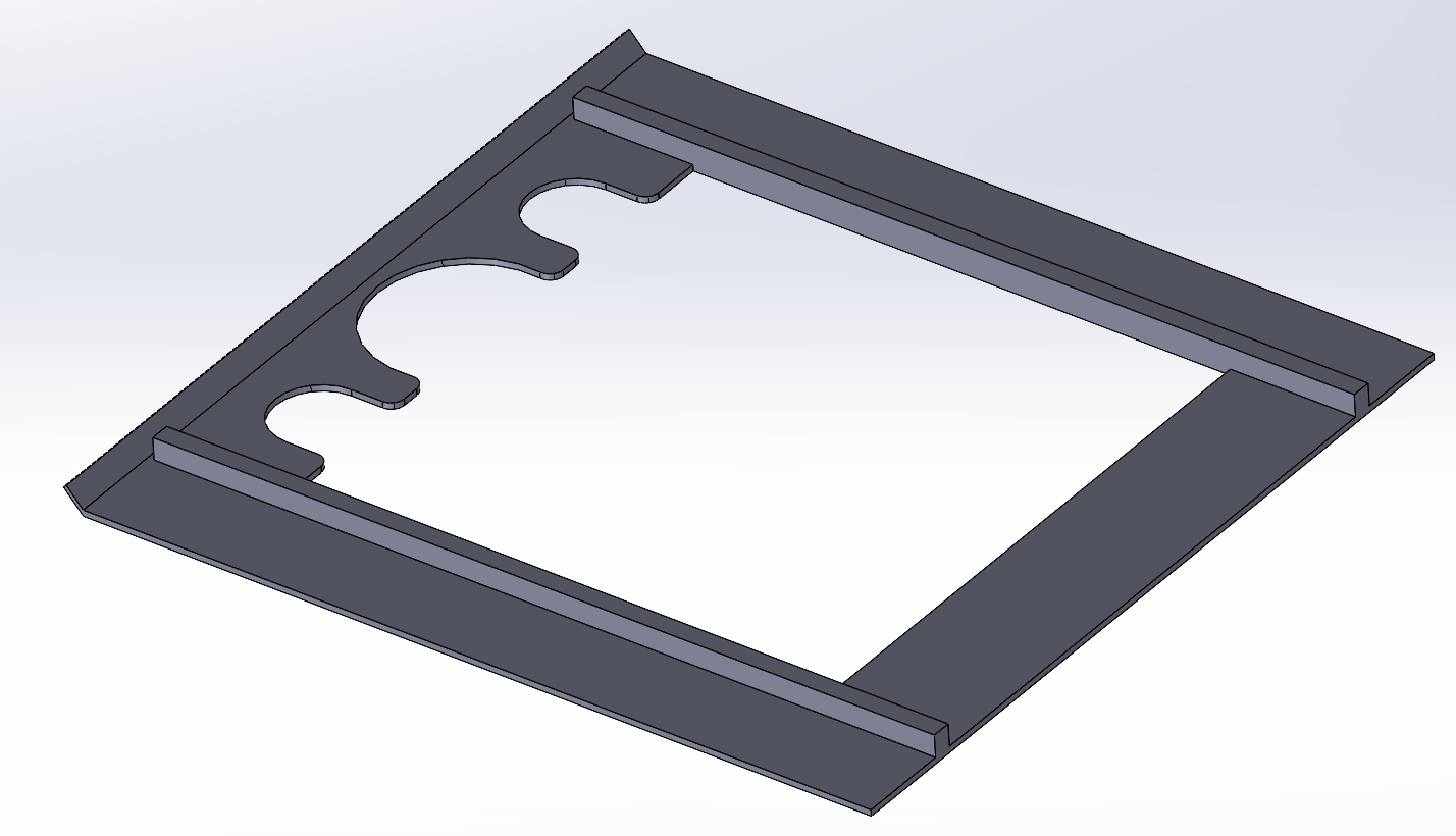
Final 3D Printed Skirt - CAD
This is the exact one used for final testing, noting that the extra cutouts were for PCB through hole components sticking through the board and the roller ball cutout was made much larger.
Paired with the best impeller, this configuration yielded the best traction test results and met my requirements while staying very light since I printed with almost no infill and the actual skirt was printed at 0.5mm layer height.
Why It Was Not Used
We originally specked a more efficient motor, but a vendor mix-up forced us to use a higher-power fan motor, which disrupted our original power budget calculations significantly. While our 220 mAh 25C drone LiPos (2x 6g) should have supplied 5.5 A, we saw instability in the Pixy2.1, gripper, and motor systems
Suspecting false discharge ratings or power ratings for certain components and lacking time to verify, we dropped the suction system 3 days before competition to ensure final system reliability for game day so we could focus on completing the mission instead of optimizing.
The suction system added ~10g. While traction improvements were clear, we didn't complete full-course testing with the system, so performance impact on full complete runs remains unknown therefore it is unclear whether it would have even been worth the extra weight but comparing the PI scores on average between runs with the suction system on and off would have clearly shown which is better.
Looking back I am dissapointed I didnt get to see our robots performance with the suction system used because I spent alot of time and effort on R&D but I do think we made the right decision at the correct time to stop trying to make it work. Those last 3 days of tuning and prepping for competition day required all 5 of our brains to solve problems and that was without the suction system in the way. If we had more time it would have definitely made sense to make it work, but I am happy with the outcome of our project.
Custom Wheel Design & Optimization
I developed custom wheels using a high-friction silicone rubber compound cast into 3D-printed molds. Early versions featured ribbed rims, which caused small tracking deviations and impaired straight-line stability which greatly affected our ability to tune the PD controller and just introduced unnecessary disturbances. After testing, I redesigned the wheels with smooth rims which significantly improved linear tracking and consistency during straight runs.
The final wheel design balanced weight, traction, and manufacturing repeatability. Silicone was selected for its high static friction against course tiles, allowing us to maximize μ in our cornering speed equation, once again optimizing for the time and mass variables in the PI score equation.
The manufacturing process was pretty simple. Iterate on D slot dimension until it fit snugly on the motors D shaft then build the mold around it such that the wheel 'snaps' into the bottom to position it correctly. Then mix the silicone, place the top cap on the rim to make pouring easier, then pour the silicone into the mold until it reaches the top where there is a lip to catch any overflow. Then to remove it, use the bottom red 'plunger' to pop the rim and silicone combo out, give the rim a quick sand and use CA/super glue to bond the silicone to the PLA rim. We made a lot of these and switched them out to ensure maximum grip at all times because they did get dirty over time. Another fun hack we took from micromouse was using a tape role and rolling our wheels on it to clean off dirt and dust...it worked really well! I was surprised even with the A20 hardness of the silicone, it did not show any signs of wear and tear even when testing on the wooden track for days.
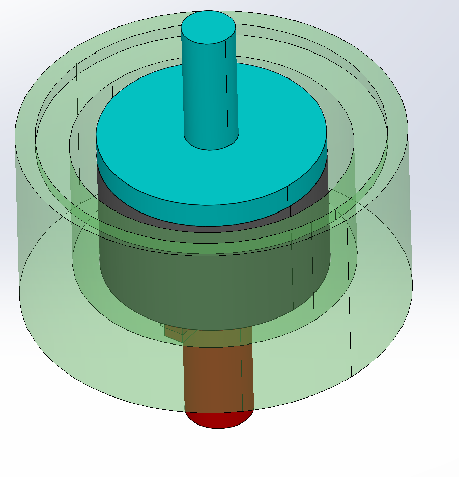
Custom Silicone + 3D Printed Wheels - Top of Mold
Red = Plunger, green = enclosure, grey = rim, blue = cover
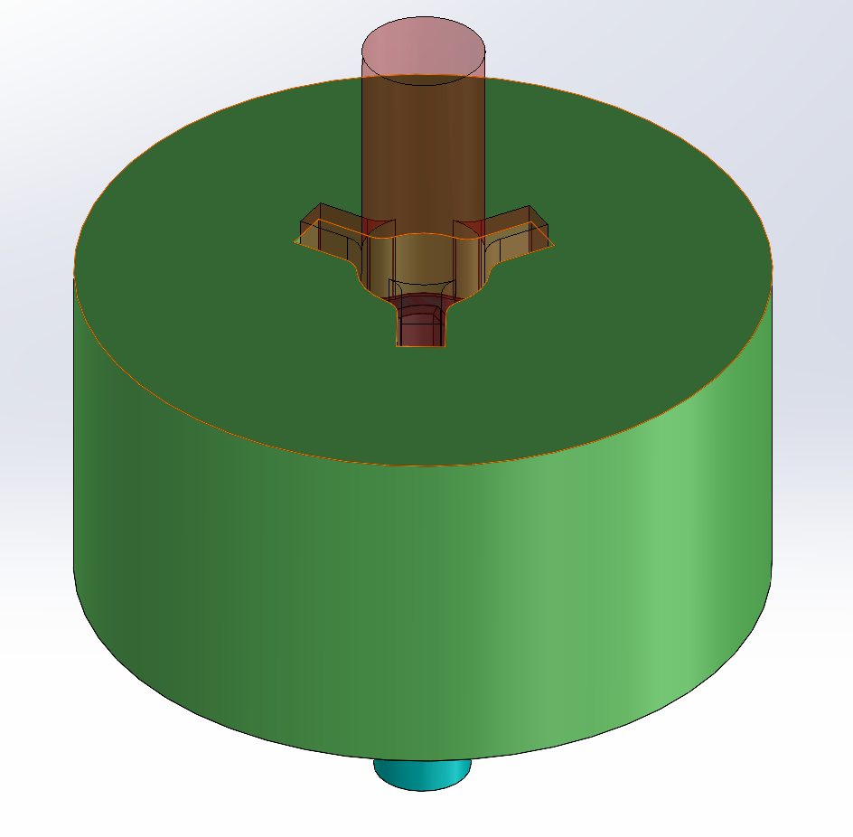
Custom Silicone + 3D Printed Wheels - Bottom of Mold
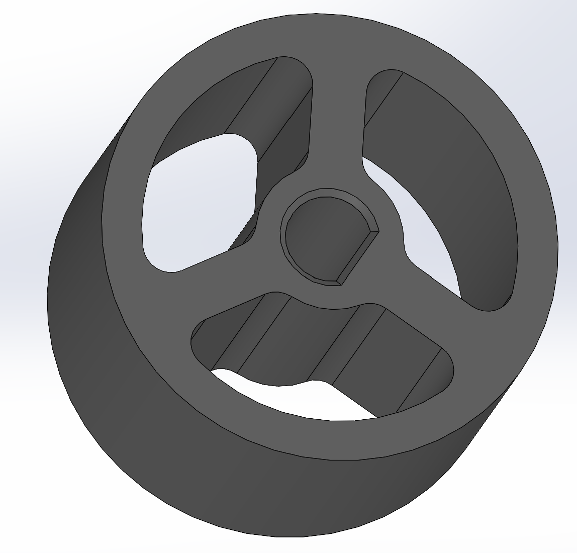
Custom Silicone + 3D Printed Wheels - Rim
21mm final OD, 17mm rim OD
Custom Silicone + 3D Printed Wheels - Bottom of Mold Enclosure
Observe the cutouts for alignment and preventing ooze out of the silicone. Also observe the rim to catch overflow at the top and cutout for the plunger.
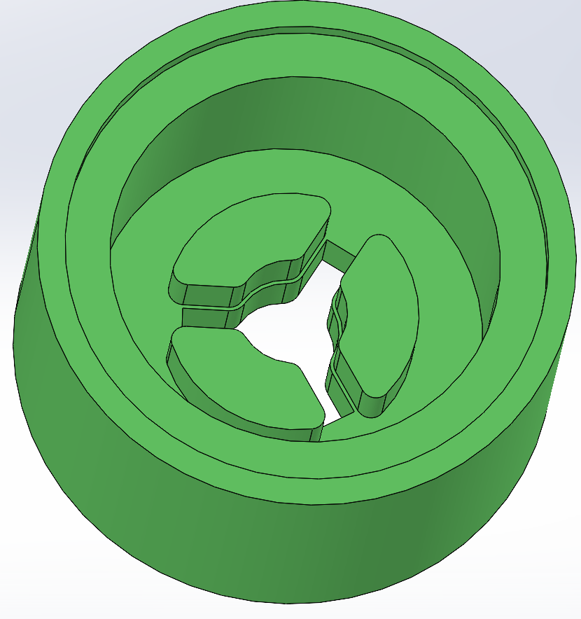
Custom Silicone + 3D Printed Wheels - Bottom of cover
Observe the cutouts for alignment for easy manufacturability
Electrical System: PCB and Power
Instead of 3D printing a chassis and putting our boards on that, we opted for the PCB to BE the chassis. We werent expecting any major loading conditions except for vibrations which we assumed the high frequency ones would be damped by the soft silicone wheels and there would be too few 'hard' impacts to affect any soldering reliability. Just in case, for the final version we opted for a lead based solder to ensure these assumptions were incorrect, once again focusing on reliability at every level.
The overall design of the PCB is summarized by the following block diagram:
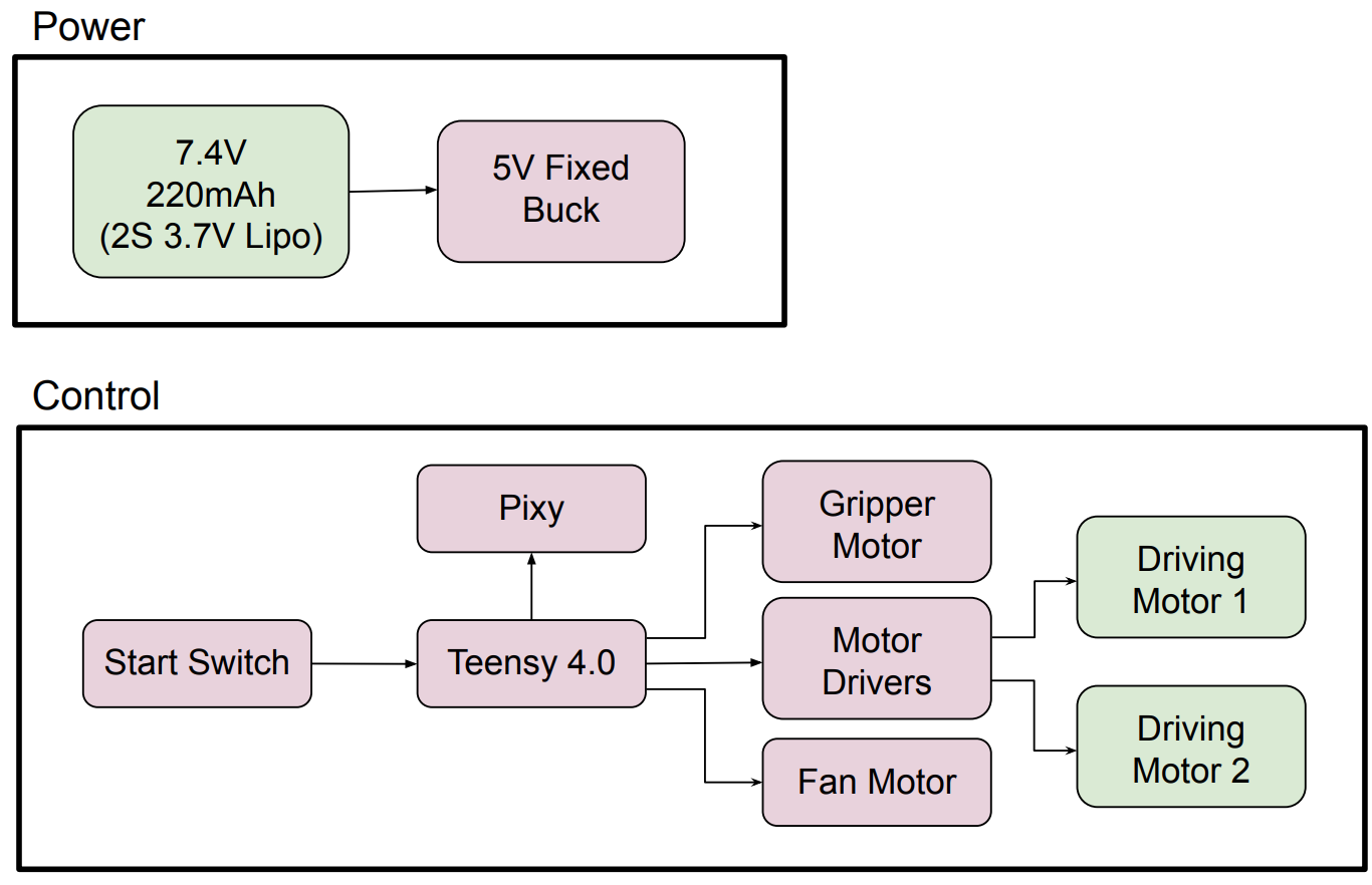
PCB High Level Block Diagram
Before bluetooth module
Features of the board:
- Teensy 4.0 MCU (SPI to Pixy2.1)
- DRV8871 motor drivers
- LM22670 buck converter (5V @ 5A)
- Simple FET drivers for fan and gripper motors
- Separate layers for encoder and communication traces
- Cutouts for LEGO and suction impeller
Power:
- 2x 3.7V 220 mAh LiPo cells (6g each)
- 80% peak current draw estimate: ~2.58 A (for everything connected to it aswell)
- Runtime need: ~43 mAh (1-minute full mission which has safety factor for peak conditions)
Here is the PCB design from concept, to block diagram, to schematic, to finished product.
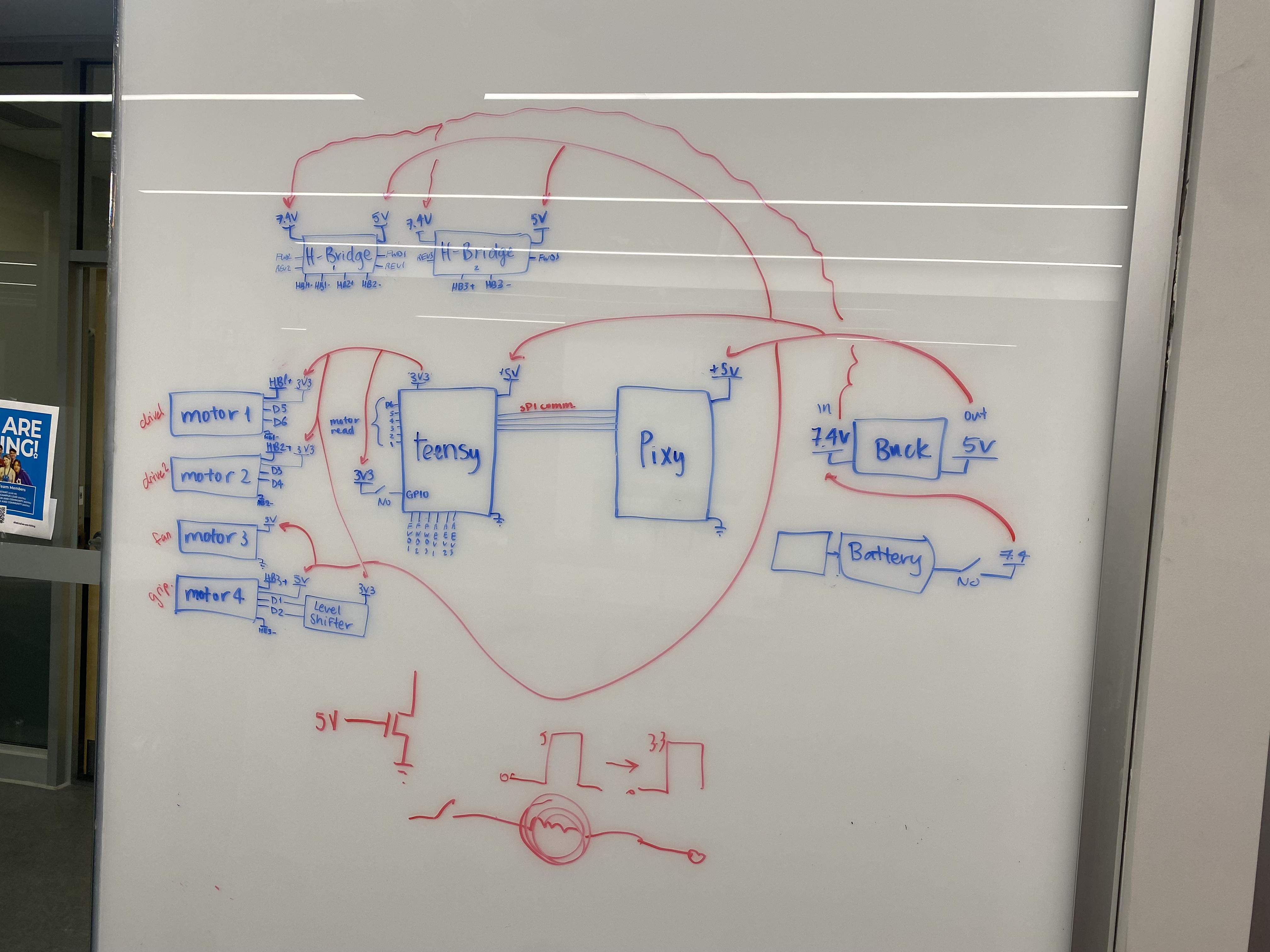
PCB Schematic Concept
Started on whiteboard with basic requirements
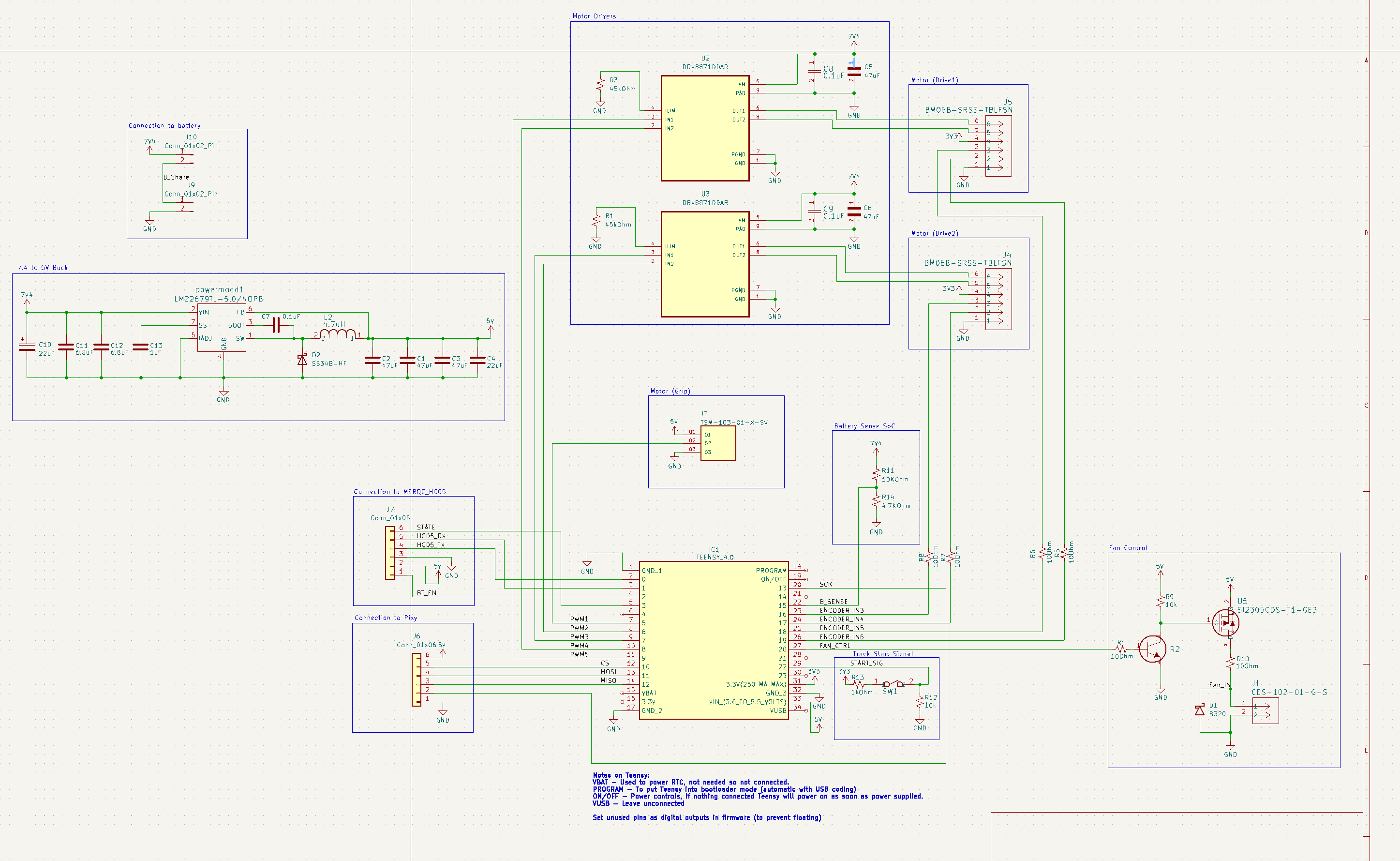
PCB Schematic
Made on KiCAD
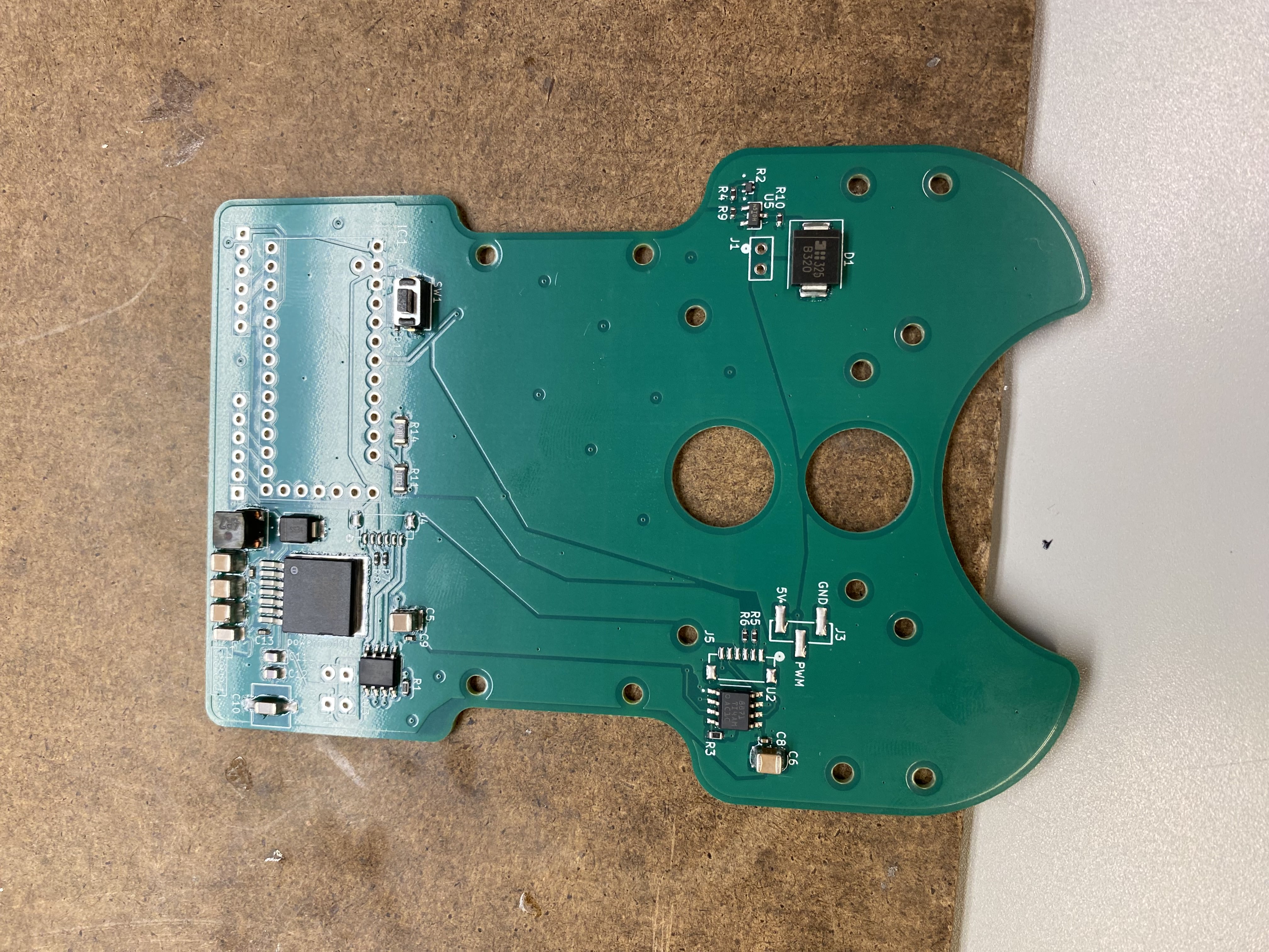
PCBA without Teensy 4.0
We used a reflow oven and hand soldered certain components so we could pick small IC packages
Schematic Download
There was lots of debugging for our initial PCB, mainly there was a servo issue which ended up being a ground pin that was floating and causing unpredictable behaviour. We figured this out through systematically tracing each pin starting from power and known working pins and working from the parts that worked to the issue. We then figured out our problem after systematic troubleshooting and grounded that pin to a nearby ground pad. There were a few other issues like backwards headers and ICs that needed a new spec due to the fan motor changing, so for PCB 2 these updates were made and there were zero issues. Also for our second version to allow us to debug in real time we added a bluetooth module to connect to the teensy instead of having to log a tonne of data which actually affected our performance early on in the development process because we were overloading the system with printing instead of allowing it to process data.
Software Architecture and PD Tuning
We used a deterministic state machine: Each robot behavior (line-follow, object detect, drop-off, return) was handled by structured conditions and transitions.
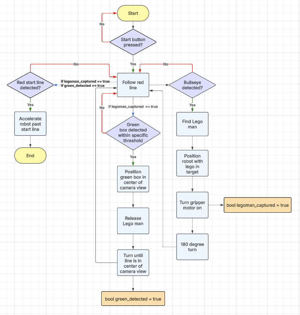
High Level State Machine
Defines the logic for our robot to complete its mission
We used PD control with the vector output from the pixy2.1 as our target and the center of the frame as our current heading then corrected the difference between them. We opted for PD and ignored I because we believed the steady state error was negligible and would only slow down our response compared to a PD controller only. The following notes about our PD control should be noted:
PD Control Highlights:
- Started with Ziegler-Nichols tuning method
- Tuned further through live tests
- Ambient lighting affected Pixy2.1 performance
- Built indoor vs outdoor controller configs for Pixy 2.1
Motor Selection
We estimated alot of parameters then did some hand calculations and ended up between the Pololu 6V Micro Metal Gearmotors (10:1 or 30:1). We opted for the 10:1 ratio since by our initial calculations, this was still overkill for our speed and torque requirements.
The motors features:
- No-load: 3100 RPM
- Torque: 0.02157 Nm
- Paired with robot mass and wheel sizing, this gave us a projected top speed of ~3.0 m/s well-matched to our goal time.
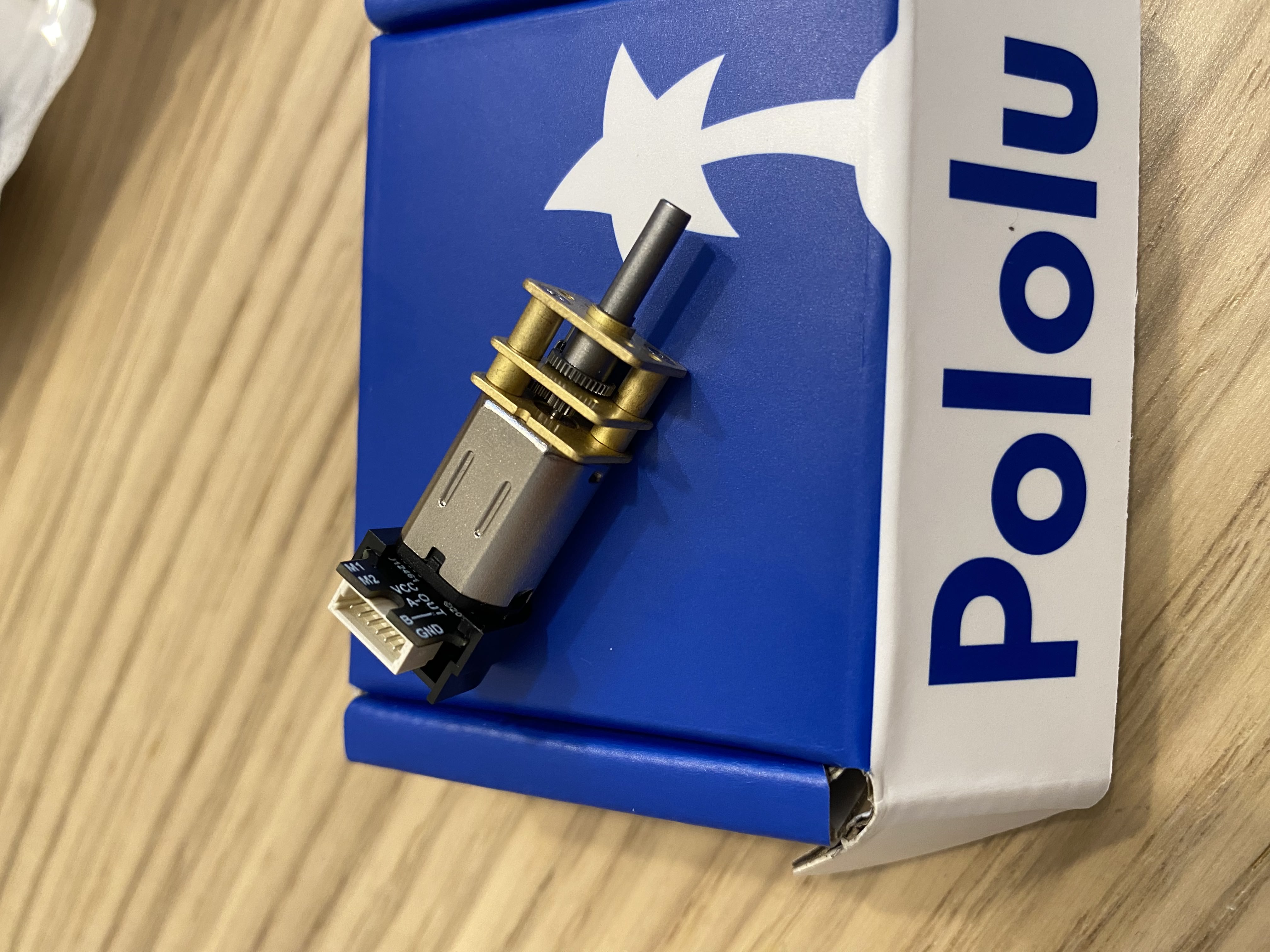
Pololu 6V Micro Metal 10:1 Geared Motor
We used 2 for the robot and they worked great. We had the pins bend at one point but after way too long of troubleshooting, we fixed it. The bracket to hold these in used the features near the gears to contrain it.
Looking back, we could only utilize PWM values above 60/255 to move our robot and anything below it did not move it. It makes me wonder where we went wrong in our calculations or if the start up low power of the motor was too low and we did not account for that. Regardless, although it made precision movements difficult, we adapted by implementing a 'jitter' step whre we pulsed at a high pwm for a short period of time and allowed us to make precision movement specifically at the LEGO figure pickup stage. This jitter was 1 huge reason for our success late in the design process and it also solved a problem we did not see coming until a few days before competition so it required lots of creative thinking. We also only utilized up to 105/255 for our 13s run so it is clear we did not come near our peak performance capabilities, but the suction system could have helped push it further.
Final Competition Performance
| Metric | Value |
|---|---|
| Weight | 131g |
| Mission Time | 13.0 seconds |
| Reliability | 3/3 successful runs |
| Size | L: 114mm (4.5") W: 86mm (3.3") |
| Score vs. 2nd Place | 68x higher |
A key optimization was that we were the only team to stop at the closest green box, which is when the clock stopped. Other teams returned home. This small rule-based insight saved critical time.
Also, considering our potential velocity increase would have been from 1 m/s (7.5s to the bullseye at approximately 7.5m long of a course) to 1.4 m/s would mean that our score could have been way faster. Also, if we could improve the pickup system that would be ideal. We found a loophole that allowed us to configure the LEGO figure with a paperclip and use an electromagnet for acquisition, but it was denied by the teaching staff unfortunately. Also, due to previous years, they also banned system that launched the LEGO figure, so physically grabbing it and moving it was the only option
Reflections
This was one of the most demanding and satisfying projects I've worked on.
Key Takeaway
- Shared team goals matter, we all built toward the same vision and committed equally
- Testing over calculations on short timelines
- Cutting scope is smart when system reliability matters and timelines are short
- Prior art matters, the micromouse projects and competition accelerated our overall design as well as other academic research papers on line following robots
- Simple systems are more tunable, debuggable, and scalable
If you want to read the full technical report, please download here…it still feels like we could have written double what we did in the report, but we were limited to our page count, which we already exceeded with this submission. So please, if you have any questions reach out and I would love to explain our thinking or answer questions! If you are doing a similar project and you came across this goodluck! Reach out and tell me about it, I would love to hear how you are approaching it and what kind of optimizations you made! Also side note...I could have probably added 100 more pictures and a couple hours worth of testing videos but I only added the really really key points here!